
Repairing Electrical Connectors
Part of
the Flexowriter pages
|
Repairing Electrical Connectors
Part of
the Flexowriter pages
|
|
|
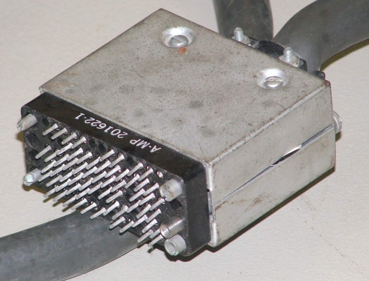
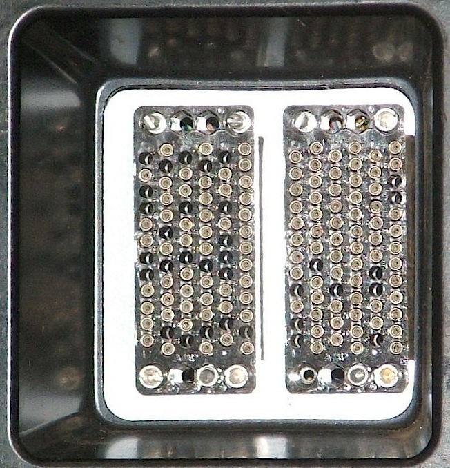
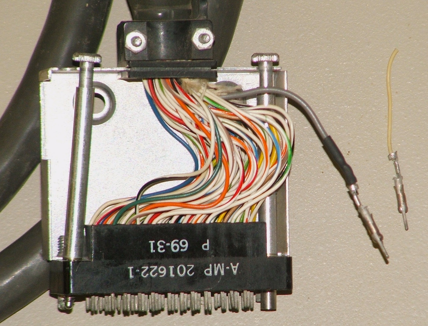
| The 75-pin plug and sockets | |
|---|---|
This plug is intended to plug into one of the two sockets on the bottom of the Model 2201 Flexowriter. Looking at these sockets in the right photo, you can see that both sockets are missing their forward jackscrew (the top one in the photo) and one of the plugs is missing a polarizing pin.
These connectors were made by AMP (now part of TE Connectivity, Tyco Electronics), and both the Flexowriter and auxiliary paper-tape reader contain a number of similar connectors, with different numbers of pins, used to interconnect the wiring harnesses of the different subsystems that make up the machines.
In addition to part numbers, these connectors are stamped with
quality-control date codes of the form YY-WW, where YY is the year
(in the 20th century) and WW is the week. These date codes set a lower bound
on the date of manufacture of our Flexowriter.
We contacted TE Connectivity about the 201662-1 connector block. They say that this part was discontinued in 1995, along with its entire series, and they offer no additional information on it.
A search of the current connector catalogs from TE-connectivity shows that this connector resembles an AMP M Series Pin and Socket Connector. The pin spacing and geometry of the 75-position housing, M-series part number 201310-1 appears to be a close match for our connector. although the housing thickness (0.915") is considerably more than the thickness of housing for the flexowriter (0.770). The diameters of the holes that house the connector pins are the same (within the error of our measurements), but the position of the smaller-diameter retaining ring within the hole is different.
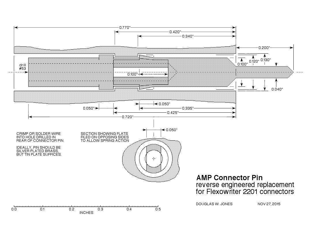
The dimensions of the AMP M-series pins, 0.062" diameter by 0.472" long, however is much larger than the dimensions of the pins in our connectors, 0.040" diameter by 0.200" long. It appears, therefore, that we will have to manufacture a replacement pin ourselves.
|
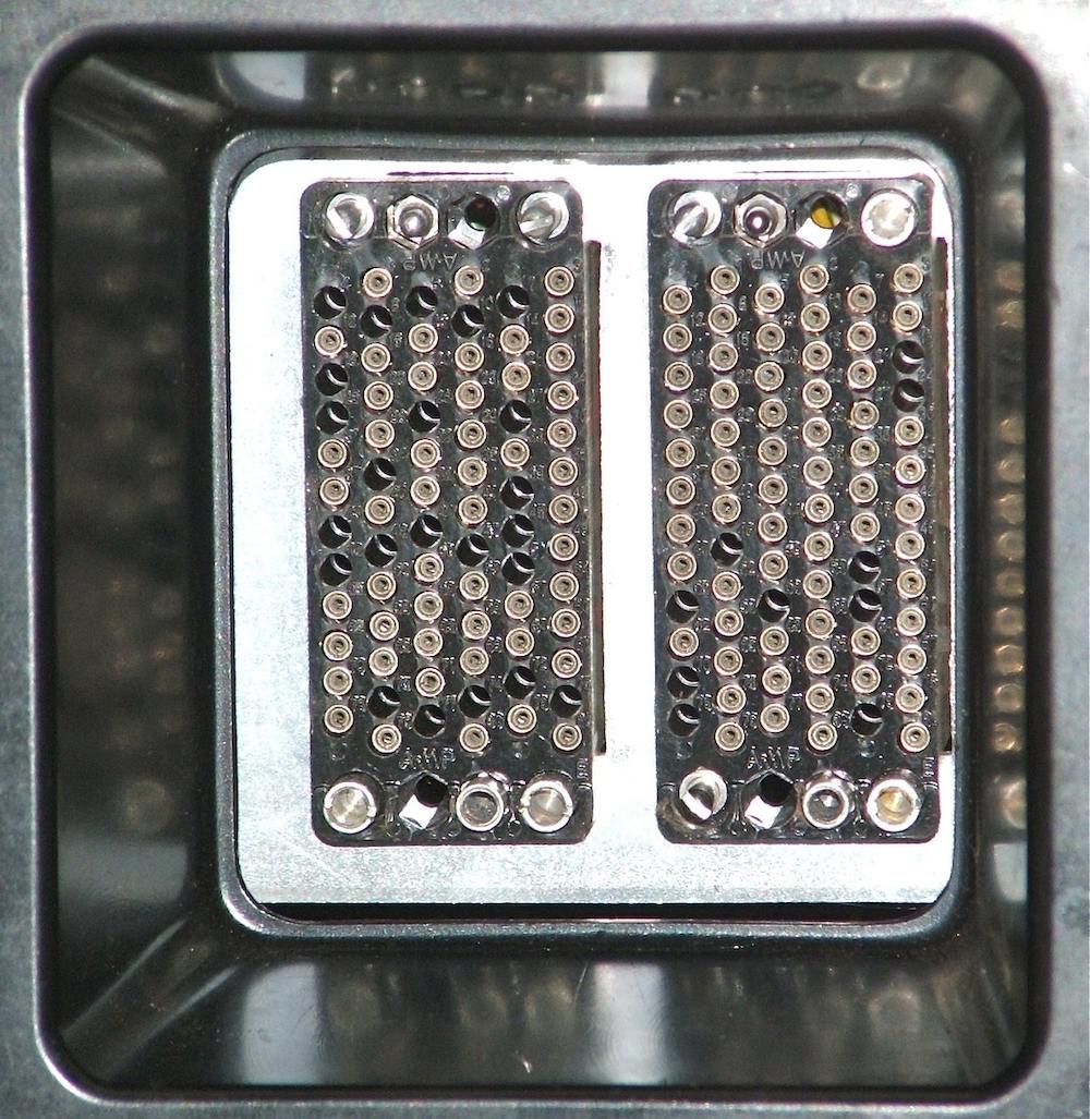
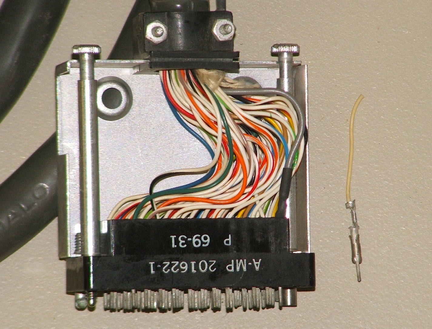
| Repaired sockets |
|---|
The photo shows the repaired socket with the replaced jack screws and corner
guide pin.
The guide pin was easy to install, but to install the jack screws, we had
to work through a thick layer of wiring. It is obvious that, during initial
assembly, these screws were installed before the connector pins
(with wires crimped in place) were inserted into the plug block. We used
two-sided foam tape on the end of a coffee-stirrer to manipulate the nuts onto
the backs of the jack screws, and then we used a jeweler's screwdriver to prod
the nuts, tightening them. Finally, we used the hardened edge of the
jeweler's screwdriver to dig into the relatively soft steel of the nut from
an angle so that we could gently hammer the nut tight.
|
|
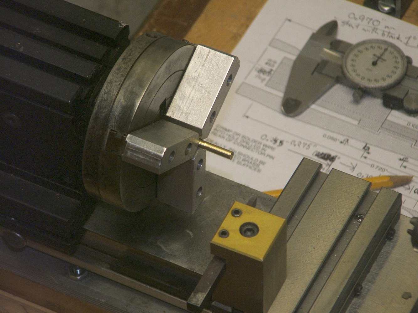
| Pin drawing and setup | |
|---|---|
|
|
| Replacing the broken pin | |
|---|---|