
The University of Iowa's DEC PDP-8Restoration Log
Part of
the UI-8 pages
|
The University of Iowa's DEC PDP-8Restoration Log
Part of
the UI-8 pages
|
Bug 64: In preparation for an open-house, we decided to start a serious attempt at tuning the memory. We began by investigating the behavior of the memory as we varied the slice voltage. For each slice voltage we tested, we stored 32 consecutive 00008 in memory starting at address 60008 and then examined memory to see how many values were still zero, and then we stored we stored 32 consecutive 77778 to see how many values were still all ones.
| Voltage | not 0000 | not 7777 |
|---|---|---|
| 7.7 | 32 | 0 |
| 7.68 | 19 | 0 |
| 7.62 | 17 | 0 |
| 7.6 | 13 | 0 |
| 7.56 | 0 | 0 |
| 7.5 | 0 | 13 |
| 7.54 | 0 | 13 |
| 7.4 | 0 | 15 |
| 7.1 | 0 | 32 |
The slice voltage was adjusted by turning the topmost trimmer on the G008 Master Slice Control board. In adjusting this and other Bourns TrimPot trimmers on DEC flip-chip modules, we have observed that the voltage is quantized, changeing in discrete steps as the trimmer screw is turned. We wonder if the trimmers are wire-wound with a contact brush touches one turn at a time.
The voltage readings here were eyeballed off of an analog meter, so the accuracy is probably 0.02V at best.
What is clear here is that the memory only just barely works. We were hoping to find a range of slice voltages that worked and then set the potentiometer to the middle of the working range.
The working range is probably a 3-dimensional volume, with the dimensions being
The next memory tuning exercise will involve playing with the other two dimensions.
With memory working as best we could adjust it, we loaded demo code in memory for the open house on Jan 20-22:
Some of the above were hand-relocated to run in new memory locations. All were tested and seemed to work.

| |
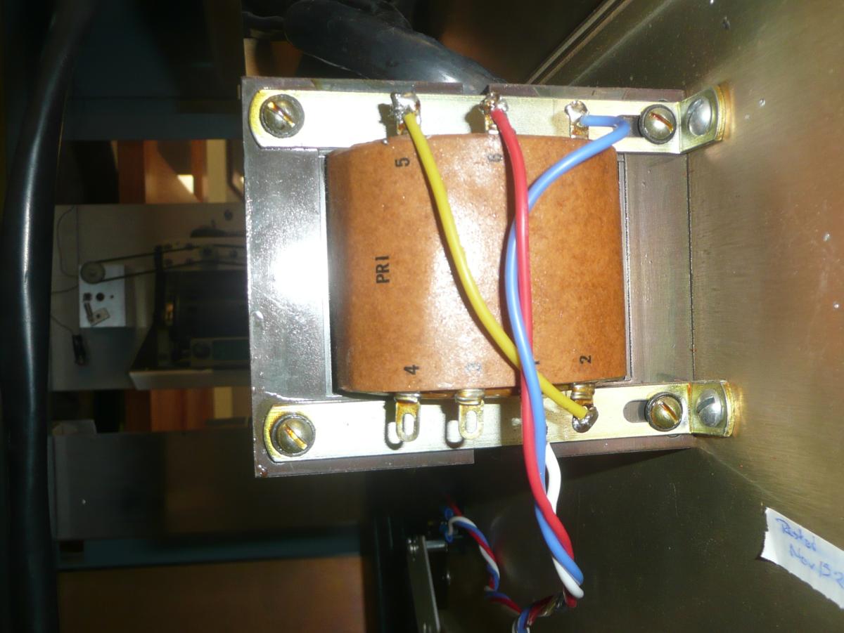
| Before and after transformer rewiring | |
|---|---|
Eliminating the bare wire jumper on the transformer reduces the hazards posed
by this power supply, but it would be nice to make a sheet metal cover over
the transformer comparable to the transformer covers on the Type 779
transformers. This will require some sheet metal bending.
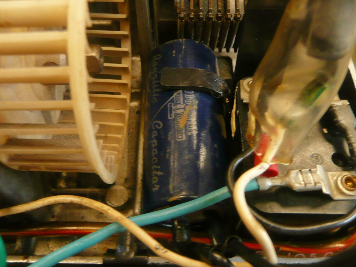
Bug 80: During a demo, after turning off the Teletype, when we turned it on again, the motor did not spin. It buzzed, and when you turned the fan, you could feel it vibrating. This implies that there is power to the motor. It is a capacitor start motor with a starting relay. Teletype's schematic FS-10 MOTORS documents this and several other motor options. Any of the following could cause the motor not to spin despite there being power to the motor:
We pulled the quick-connect connectors to the starting relay, allowing us to use an ohm-meter to verify that the primary motor windings is 9Ω and the starting winding is 16.5Ω ruling out a burnt-out motor winding. Measuring between the primary and starting widings, have 25.5Ω, so there are no shorts between the windings.
| |
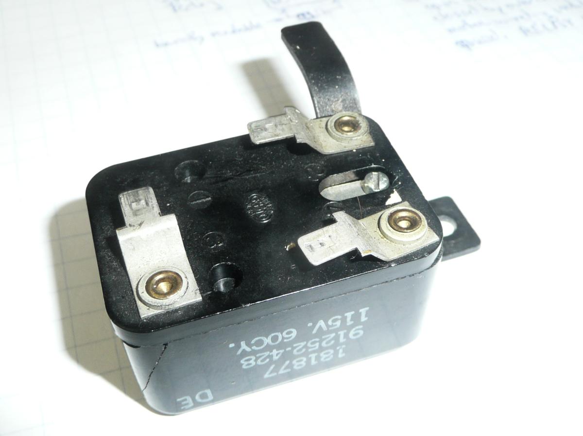
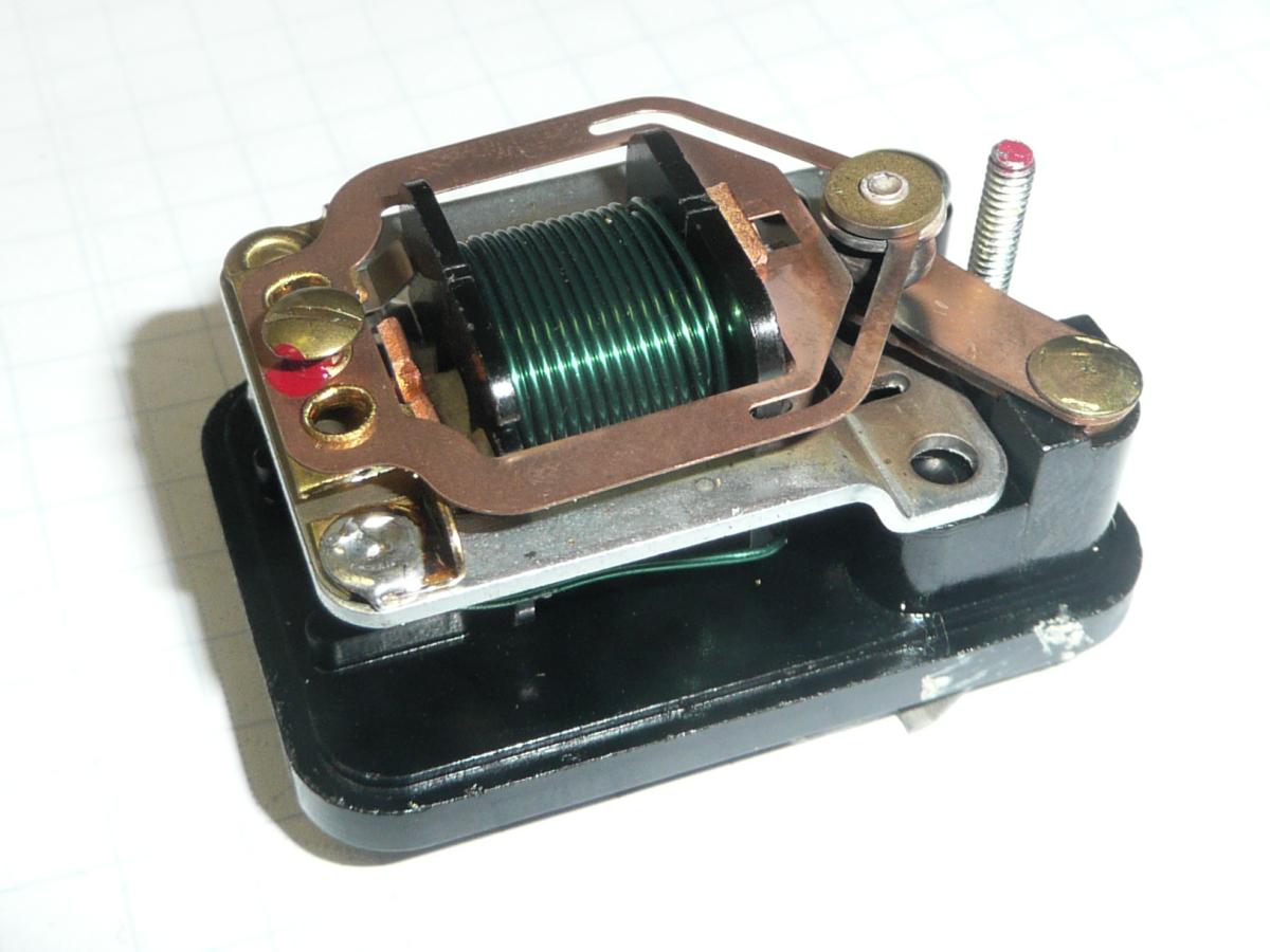
| The Teletype motor start relay | |
|---|---|
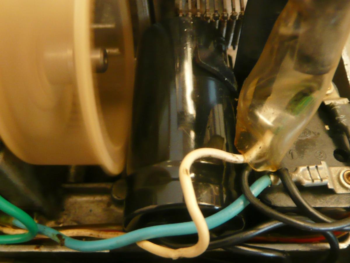
The relay is a normally open relay with an approximately 0.1Ω coil. During the motor's starting surge, the relay closes to power the starting winding. Once the motor is up to speed, the current through the primary motor winding is too low to hold the relay closed. Aside from evidence of contact arcing, the relay is in good condition. We burnished the contacts and put the relay back. We did not make any changes to the adjusting screw (the screw on the left of the right photo with a red dot of paint on it).
After reassembly, we used an ohm meter to verify that the start relay closes when power is briefly applied to the motor.
The above observations point to the motor start capacitor itself. Teletype's schematic identifies this as C3 88-108, which agrees with the markings on the capacitor, 88-108MFD. This is an 88-108μF capacitor, a very common value of motor start capacitor.
Bug 80: Continuing the diagnostic work from Jan 22, we used an analog ohm meter on the Rx1K scale to test the 88-108μF motor-start capacitor. It conducts very briefly when the meter leads are first connected and then drifts up to infinite resistance. That is how a capacitor ought to behave when measured this way. We compared it with a known good 5μF capacitor, and saw that the response on the ohm meter was far stronger with the latter than with the capacitor from the Teletype. Therefore, while the capacitor still has some capacity, it has much less than 5μF.
So, we ordered a replacement capacitor. The original capacitor was a 1" (26mm) diameter cylinder 2.5" (65mm) long. The smallest replacement we could find was 34mm by 69mm, 8mm larger in diameter. This will be a tight fit in the space in the Teletype. Also, we will need some 4.8mm (0.187") faston connectors to attach the capacitor to the wiring. Teletype corp. seems to have used that size exclusively, while the similar connectors in the PDP-8 are all the more common 1/4" wide.


| |
| Before and after transformer rewiring | |
|---|---|
We had finished rewiring the transformer primary. Now, we rewired the secondary, moving the fuse to the bridge between the two secondary windings and finishing adding spiral-wrapped insulation to the remaining uninsulated wires.
We still need to install metal shields to protect fingers and make accidental
shorts less likely. This is most important on the 120V primary side of the
transformer, but would also be helpful on the 30V secondary side.

|
| Decayed foam |
|---|
Bug 64: We returned to the memory tuning problem last addressed on Jan. 14. We connected the current probe and began trying to adjust the inhibit and read-write (or select) currents. We found that the inhibit current was 0.28A, not the recommended 0.31A. We were able to bring it up to 0.295, but no higher.
We also found that the select current was also low. We were able to turn it up to 0.32A.
With these changes, we repeated the exercise we had done on Jan. 14, varying the slice voltage, and at each step, writing 16 consecutive words of 00008 and 16 consecutive words of 77778 to memory and reading them back. On Jan. 14, only one slice voltage worked, 7.56V. Our changes to the select and inhibit currents made a big difference:
We left the slice voltage set to 7.72V, roughly the middle of the good range.
|
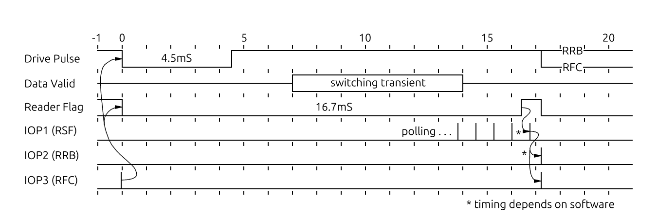
The 16.7mS delay between initiation of a read cycle and the setting
of the device flag allowing initiation of the next cycle is also from the
Tally manual. The role of the RSF, RRB and RFC
instructions and their relationship to the reader flag and the rest of the
read cycle is from the description of the Type 750 High Speed Reader
interface on
pages 62-63 of the
PDP-8 Users Handbook,
Digital Equipment Corporation, F-85, 5/66, 1966.
From this timing diagram, we conclude that our speculation on
July 1, 2025 that only 2 delays
are required seems correct so long as the reader flag is only set
after the full 16.7mS read cycle, at the earliest time that it is acceptable
to start the next read cycle. Given that software should only take a few
tens of microseconds to initiate the next read, this should not appreciably
slow the reader. It would be possible, at the cost of considerable complexity,
to read the input into the reader-data register and set the reader-ready flag
at the end of the switching transient, 14mS into the read cycle. This would
require an additional delay and an additional flipflop to allow the
RFC to queue up starting a read cycle before 16.7mS have elapsed.
| |
| Old and new starting capacitors | |
|---|---|
So, we hunted for new parts. While 88-108μF capacitors are available, they tend to come in large packages. The smallest motor start capacitors we could find were CD60 100μF &plusminus; 15% rated at 250VAC. Among these, we found some with bodies 34mm diameter by 69mm or 70mm long with wire terminals comparable to the originals. Most modern motor starting capacitors are polyester film and not electrolytic capacitors, and we think this applies to the capacitor we bought.
Polyester film capacitors are generally larger than electrolytics, and in this
case, the difference in size is enough that we were not certain that the
new capacitor would fit. As can be seen in the photos here, the new
capacitor just fits. We had to bend the hold-down finger that extends from
the starting relay mounting bracket to make it fit, and there was just over
1mm clearance between the new capacitor and the fan on the back of the Teletype
motor. Fortunately, the capacitor is tightly held and does not threaten to
bounce into the fan, and as the photo shows, the fan spins freely and the
Teletype works well.
Bug 16: Now that the homebrew reader-punch power supply works and our estimate of power demand made on Dec. 11, 2025 suggests that it will not overtax the PDP-8's rack wiring, we jumpered it to the line-line current terminal strip on the Type 779 power supply directly below it.
Bug 10: We have not powered up the Type 779 supply since Oct. 9, 2014 so we disconnected the fan in the base of the I/O rack and disconnected the wiring from the supply to the logic in the rack and then connected it to a variac so we could slowly raise the voltage.
The ferroresonant transformers in the Type 779 supply created a very nonlinear relationship between the output voltage and the setting on the variac. Under no load, the DC output voltages on the Type 779 supply approached their rated values at AC input voltages under 50 volts. Fortunately, the capacitors we had reformed a decade ago were in pretty good shape, and we saw no ill effects from raising the output voltage in 5V steps about an hour apart.
We paused periodically to check for leakage by looking at the rate of decay of the charged capacitors with no power input and no load. We were briefly alarmed to discover that the +10 output of the Type 779 supply was decaying rapidly, until we noticed that there is a 15Ω resistor shunting a 35,000μF capacitor to ground for that output. output to ground. This matches the Type 779 Power Supply schematic. The RC time constant for this capacitor is 35,000μF×15Ω = 0.525s. By eyeball, watching the needle of an analog volt meter drop as we turned off the power, it fell most but not all of the way to zero in about a second, which is in the right order of magnitude for this RC time constant. We conclude, therefore, that the supply is good.
Note:
Ferroresonant transformers
are well known to hum louder than other transformers, and in our Type 779
supply, we noticed this hum, starting when the AC input was around 30V and
getting louder as the AC input was ramped up to 120V.
Bug 43: With memory working better, we tried keying in a more ambitious program from the front panel. Of course, we made mistakes in the code and mistakes in the keying in. We debugged the code using a Linux-based assembler and PDP-8/E emulator before trying again. The following code worked:
           / Teletype demo (poorly optimized code)
           / Typing char echos and appends char to buffer except
           STX=    202             / Control B -- clear buffer
           ENQ=    205             / Control E -- replays buffer
           *4000
04000 7200         CLA
04001 1253         TAD     PBUF
04002 3260         DCA     INPTR   / bufptr = start
           LOOP,                   / loop -- outer loop of program
04003 6031 INPOLL, KSF             /    loop -- polling input
04004 5203         JMP     INPOLL  /    until -- key pressed
04005 6036         KRB
04006 3256         DCA     CHAR    /    char = character from tty
04007 1256         TAD     CHAR
04010 1254         TAD     NEGSTX
04011 7440         SZA             /    if char = STX
04012 5216         JMP     NOTSTX
04013 1253         TAD     PBUF
04014 3260         DCA     INPTR   /       bufptr = start
04015 5203         JMP     LOOP    /       continue
04016 7200 NOTSTX, CLA             /    endif
04017 1256         TAD     CHAR
04020 1255         TAD     NEGENQ
04021 7440         SZA             /    if char = ENQ
04022 5242         JMP     NOTENQ
04023 1253         TAD     PBUF
04024 3257         DCA     OUTPTR  /       outptr = start
04025 7200 OUTLP,  CLA             /       loop -- exit by break
04026 1260         TAD     INPTR
04027 7041         CMA IAC
04030 1257         TAD     OUTPTR  /          a = outptr-inptr
04031 7500         SMA             /          if a >= 0
04032 5203         JMP     LOOP    /             break
04033 7200         CLA
04034 1657         TAD I   OUTPTR
04035 6046         TLS             /          output *outptr
04036 6041 OUTPOL, TSF             /          loop
04037 5236         JMP     OUTPOL  /          until output done
04040 2257         ISZ     OUTPTR  /          outptr++
04041 5225         JMP     OUTLP   /       endloop
                                   /       continue outer loop
04042 7200 NOTENQ, CLA             /    endif
04043 1256         TAD     CHAR
04044 3660         DCA I   INPTR   /    *inptr = char
04045 2260         ISZ     INPTR   /    inptr++
04046 1256         TAD     CHAR
04047 6046         TLS             /    output char (echo it)
04050 6041 OUTPOM, TSF             /    loop
04051 5250         JMP     OUTPOM  /    until output done
04052 5203         JMP     LOOP    / forever

           / constants
04053 4061 PBUF,   BUF             / start of buffer
04054 7576 NEGSTX, -STX            / used to compare with stx
04055 7573 NEGENQ, -ENQ            / used to compare with enq

           / variables
04056 0000 CHAR,   .-.             / most recent input character
04057 0000 OUTPTR, .-.             / buf pointer to output buffer
04060 0000 INPTR,  .-.             / buf pointer fill buffer
04061 0000 BUF,    .-.             / start of data buffer
This is a far more satisfactory Teletype demo program than the smaller one we keyed in on Sept. 29, 2025 (that code was still in memory).
With this demo code working, we tried using the RIM loader to load the BIN loader. This seemed to work, but when we tried using the BIN loader to load ODT, the octal debugging tool, it did nothing. The paper tapes we used were from 1966 and 1967. We need to explore what happened.
Bug 62: We made a thin 1/4" hex box wrench so that we could loosen (and retighten) the screws in the linefeed drive link. See the June 29, 2017 log entry for a discussion of this adjustment and the need for a thin box wrench. Our home-made wrench is made from a piece of 1/8" thick hot-rolled steel bar. We drilled 1/4" round holes the two ends, then drove center punch that had a 1/4" hexagonal body completely through the holes. The resulting hexagonal holes were undersized because the center punch body was slightly undersized, so we further enlarged the holes be driving a 1/4 inch screwdriver bit through the hole; the screwdriver end itself is irrelevant here, what matters is the 1/4" hexagonal back end of the bit. What remained was to file off the burrs from the holes and grind and then file the outside profile of the wrench.
With our wrench made, we were able to tighten the marginally loose screws in the drive-link. These had been slightly loosened at some point in the past while trying to adjust the drive link. We solved the actual linefeed problem by careful adjustment of the drive-link up stop.