Accessories for Punched Cards
Part of
the Punched Card Collection
|
Regular users of punched cards frequently had the following accessories in or around their desks:
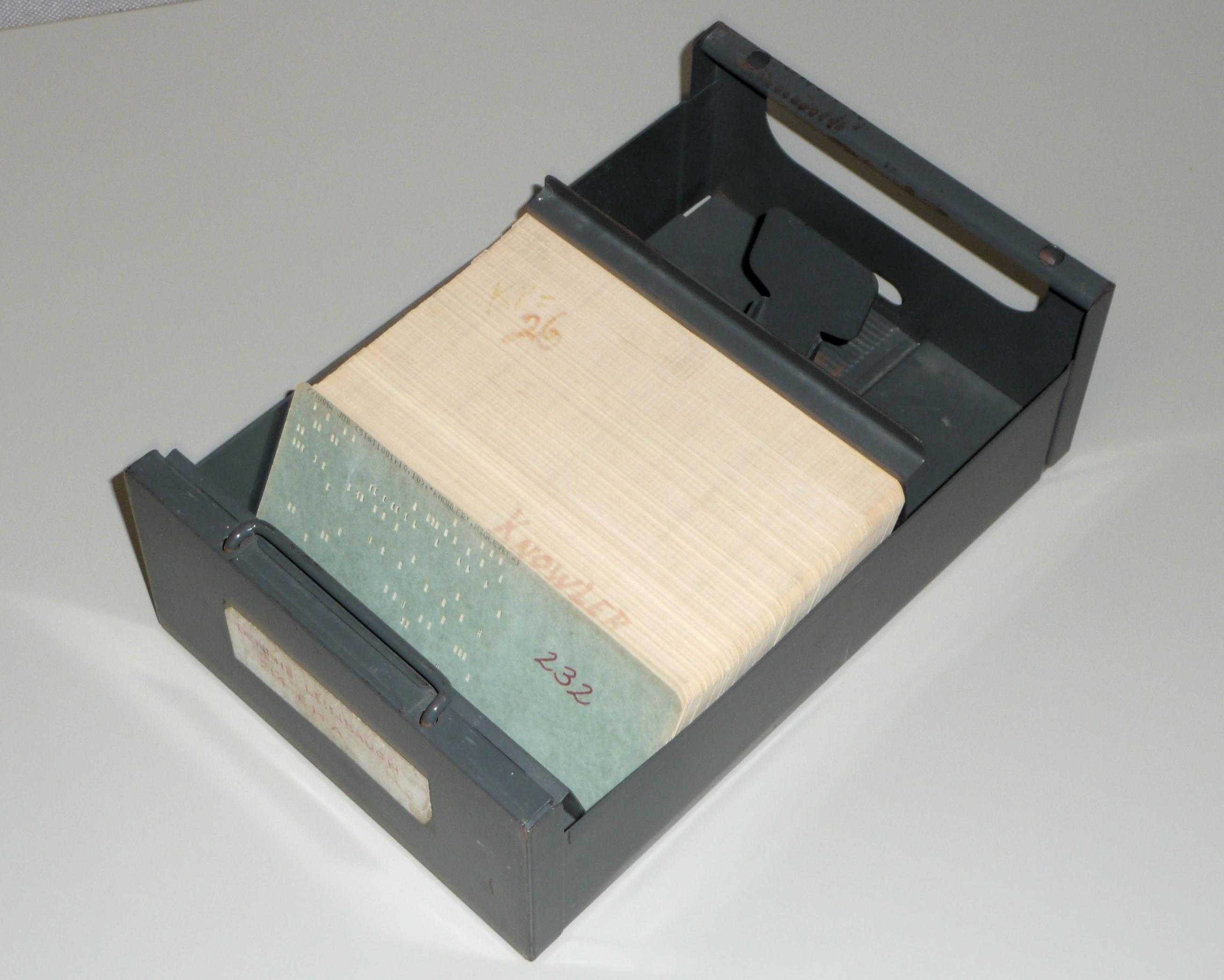
Punched cards came from the manufacturer in tight-fitting corrugated cardboard boxes of 2000 cards. Students and other card users on a budget frequently used these boxes to file their cards, but if your cards were valuable, it was worth investing in a file system. You could get filing cabinets designed to hold punched cards. These had removable card files, each able to hold either 1000 or 2000 cards.
|
|
|
|
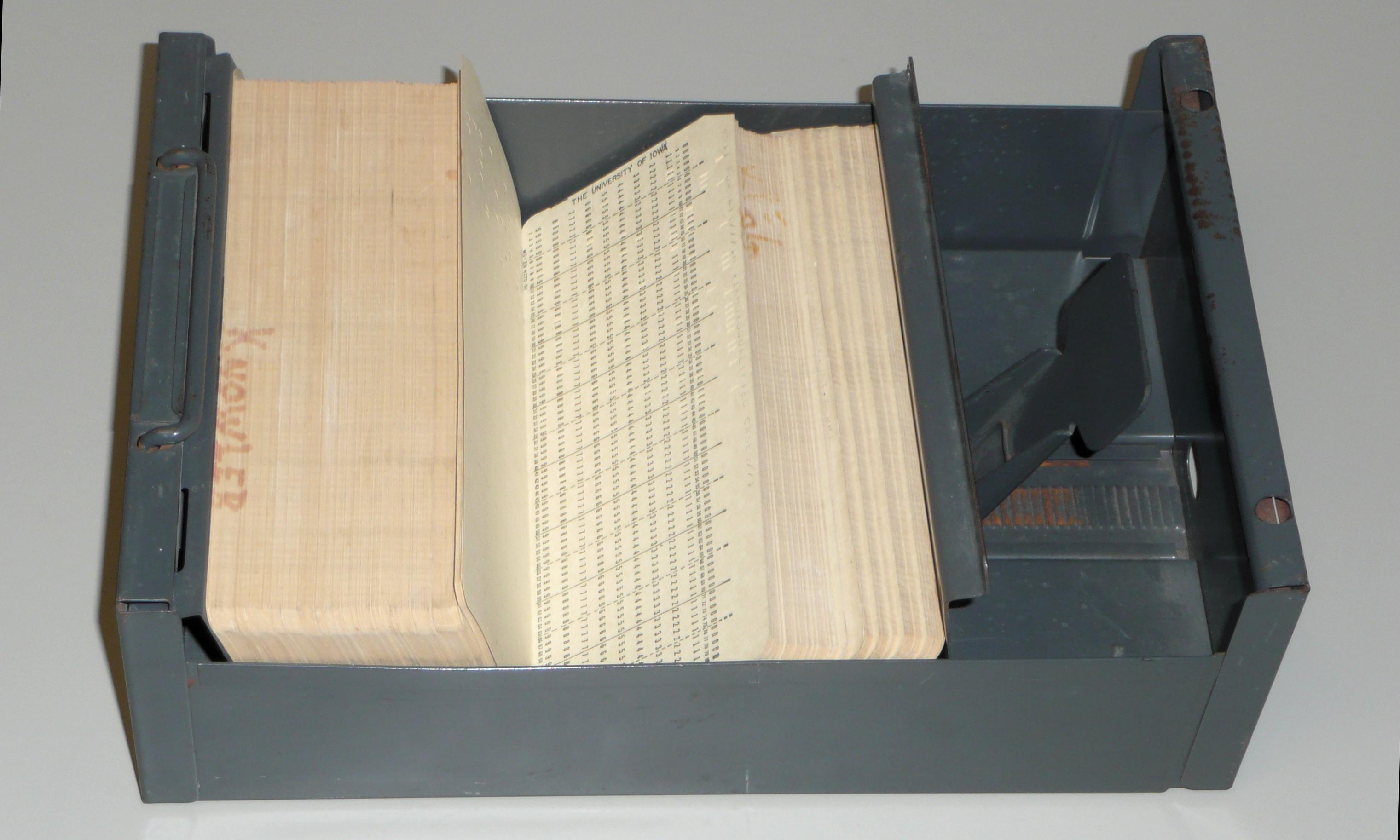
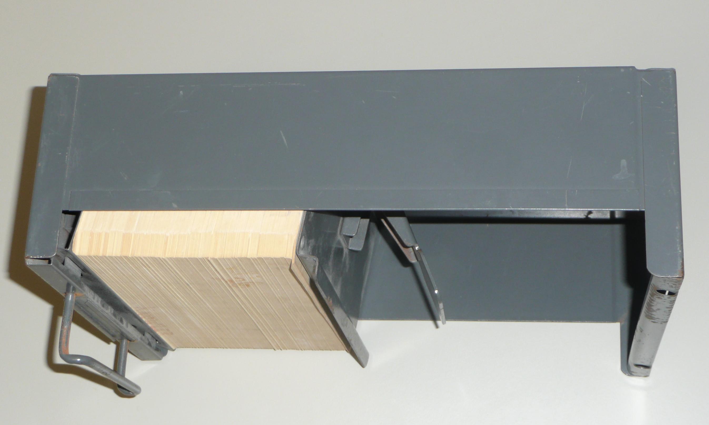
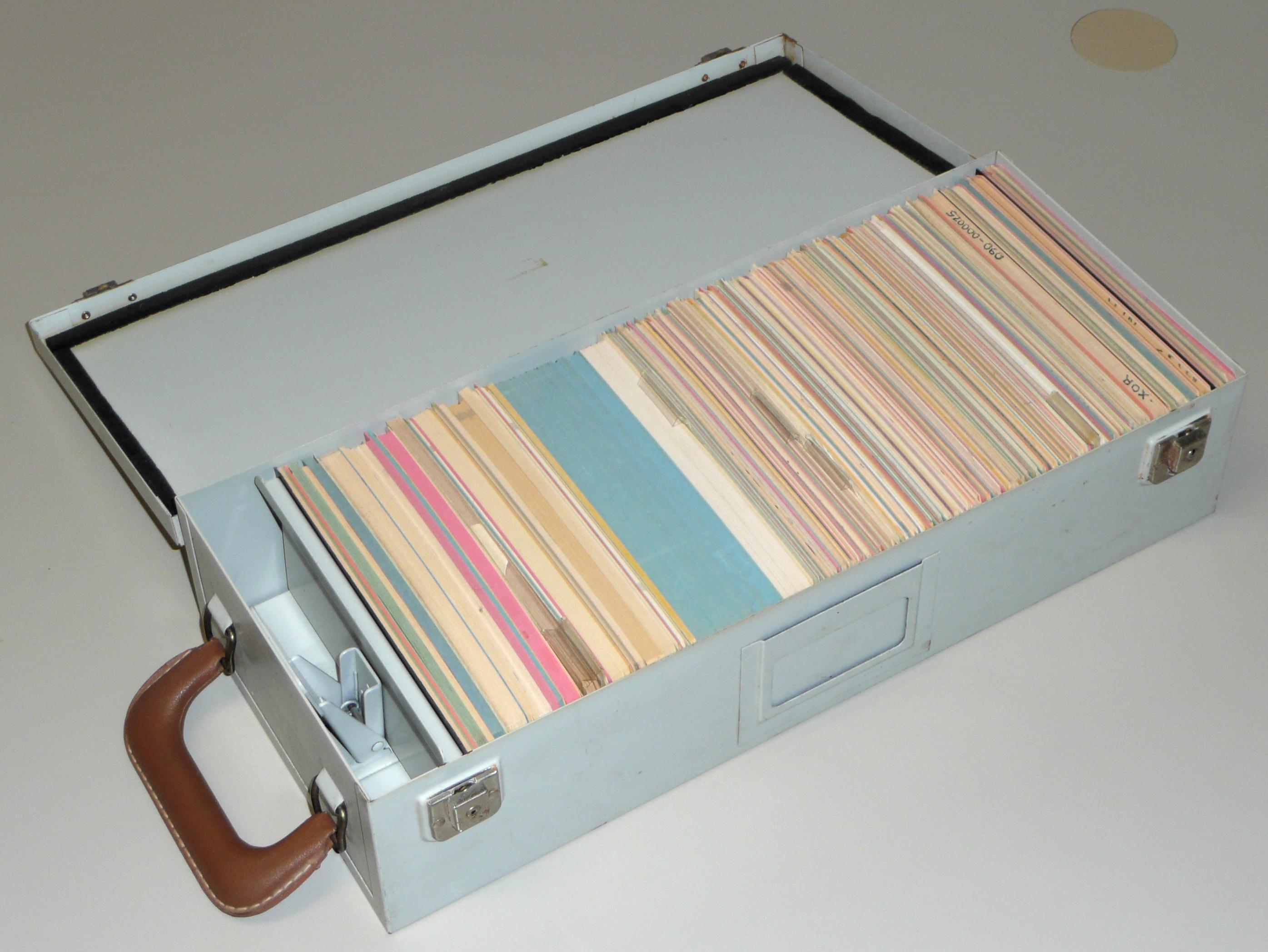
The card file shown can hold 1000 cards, and it is about half full. The file includes a sliding back plate that can be unlatched and slid back to open up the file for editing or to remove the deck of cards. When the back plate is slid tightly forward and latched, it compresses the deck of cards for secure storge.
Standard card files almost always included a carrying handle. This one includes two, a fixed handle at the back and a collapsible handle at the front. Both handles were typically used to swing the file up into its slot in the filing cabinet, but the cards were secure for carrying one-handed so long as the card deck was securely latched into the case. That's how you would carry your card file to the computer center when you wanted to run the program or process the data on your card deck.
Today, we refer to collections of data in the mass storage of our computer systems as files because much of that data is in the form of text that would, in days past, have been on punched cards, and those punched cards would have been stored in card files.
When data or programs were stored on cards, files were edited by simply adding and removing cards. The keypunches used to punch text or data onto cards were usually clustered in a keypunch room. A programmer could take the card file to the keypunch room and edit there, but if the file was large, it was common to write out the changes on paper, preferably a coding form, and then take just this to the keypunch room to punch the new cards. Sometimes, you would hand the coding form to a keypunch girl (they were almost always women) who would punch the new cards, but many programmers punched their own cards. After punching, you would carry the new cards back to your office to update your card file.
The deck of cards in this card file holds a FORTRAN program perpared by Professor Lloyd Knowler (1908-1990) of the University of Iowa. Knowler was a statistician, and this program no-doubt does something related to his work.
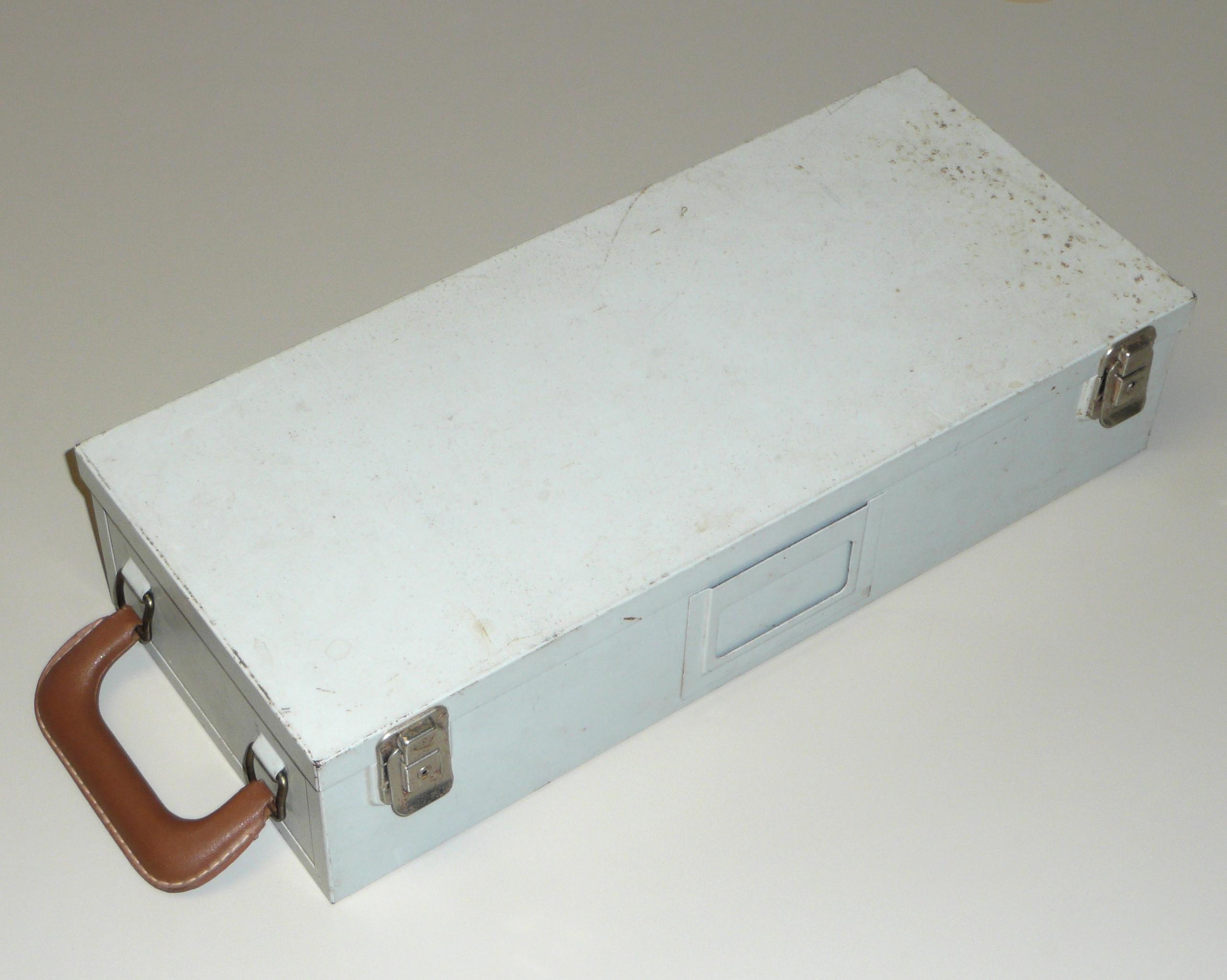
Card files were not weatherproof, so if you had to carry your cards outside in bad weather, a card file was not enough. While students and those on a tight budget might carry their cards under their coats for protection, those with money could buy specialized luggage.
|
|
The card case shown has a leather-bound suitcase handle on one end. The case has a capacity of 2000 cards, and the interior is the same as a standard card file of that size, including the sliding plate to securely compress the cards.
Aside from the carrying handle, the important feature that distinguishes card cases from standard card files is the hinged and gasketed lid. While the lid is probably not truly waterproof, the case is easily able to defend agains spray, snow or light rain.
The cards in this particular case are the punched card collection featured here.

|
Vendors of punched card printing services provided convenient forms on which customers could design new punched card layouts. This multiple card layout form has room for 6 different cards. Someone has used row 1 of this form to design a "check deduction card," presumably part of the payroll system for some company.
It was very common to design multiple cards for one company so that fields that had the same meaning used the same card columns. In this example, the fields reserved for "branch" and "emp no" have been carried down through all 8 lines of the form. In addition, column 1 has been reserved for a one-digit tag to indicate the format of the remainder of the card, with the "check deduction card" assigned number 8 in this field.
The form is from Mechanized Accounting Inc. of Pittsburgh. It is likely that the form could be submitted to any custom punched-card printer, but apparently, Mechanized Accounting had a relationship with Globe Ticket Company, one of the major supplier of custom-printed punched cards. The form came with a collection of paperwork and cards from the early 1950s.
|
|

|
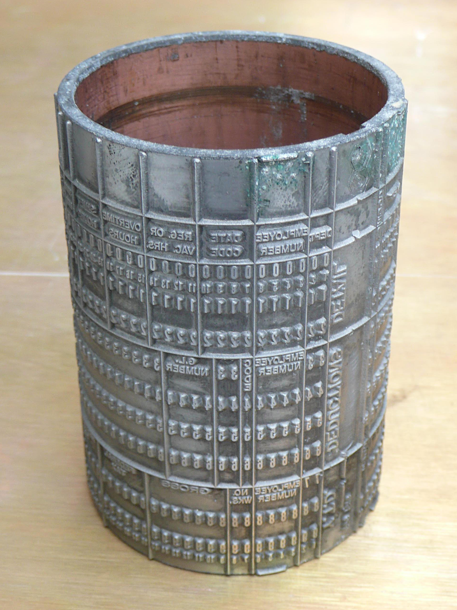
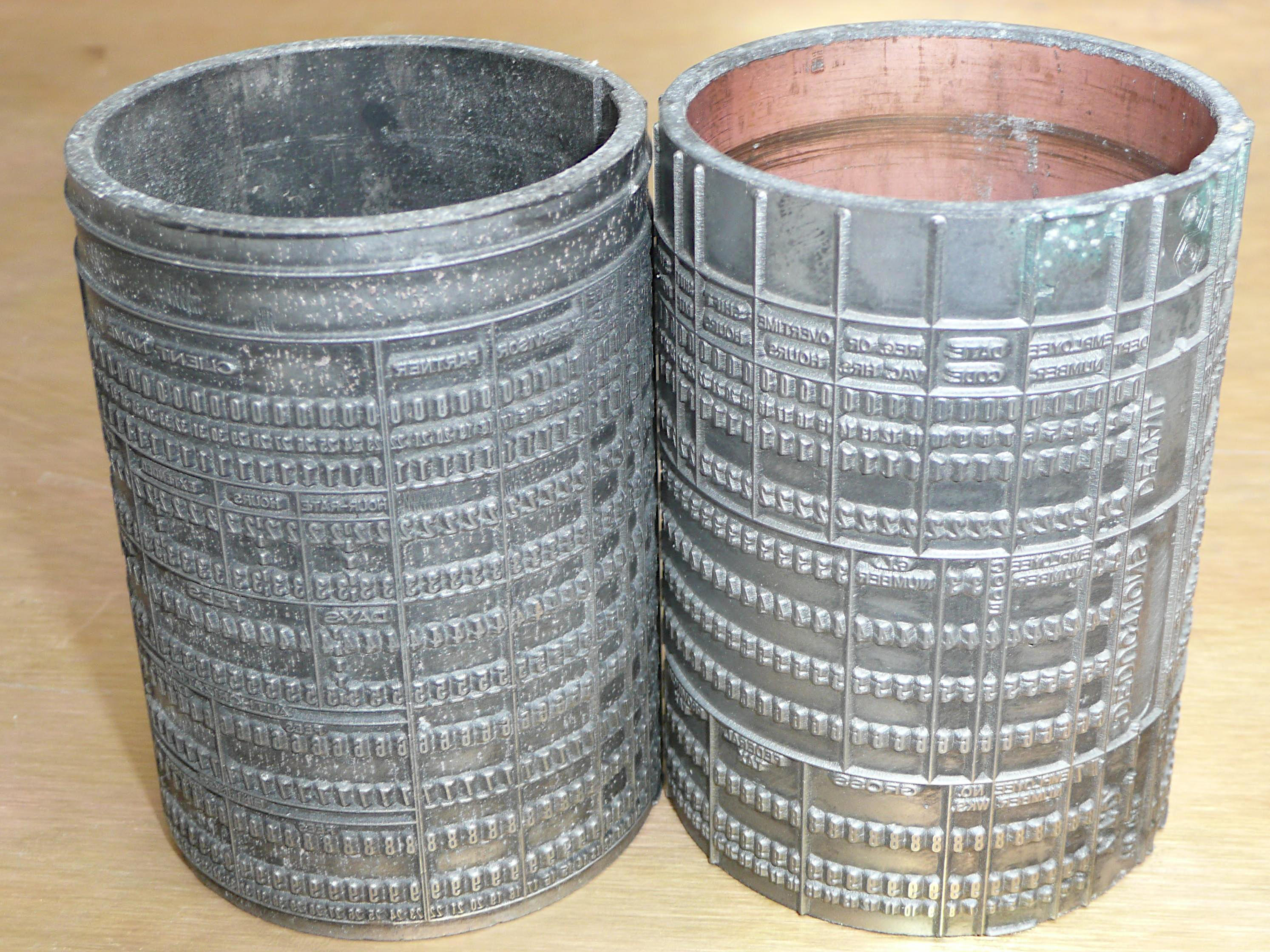
Punched card printing plates were formed into cylindrical drums. Each turn of the plate printed one card on the long strip of paper fed into the press. The press automatically cut the strip into cards immediately after printing, and then stacked the cards on an output tray, stopping after 2000 cards so that the stack could be slid into a card box for shipping to the customer.
The printer generally retained the printing plates until they were worn out or became obsolete. Used plates could, of course, be melted down and made into new plates, but many used plates became souveniers. Punched-card purchasing managers were the most likely to get such plates, but the programmers who designed the data formats for the cards were also likely to end up with the plates for the cards they designed. Used plates really had only one practical use: They made excellent pencil holders.
Both of the plates shown here are for forms involving employee and payroll records. They don't correspond to any of the cards in the collection, which is not at all surprising. Cards were produced in immense numbers for over half a century, and the number of different forms used in this period was astronomical.
|

|
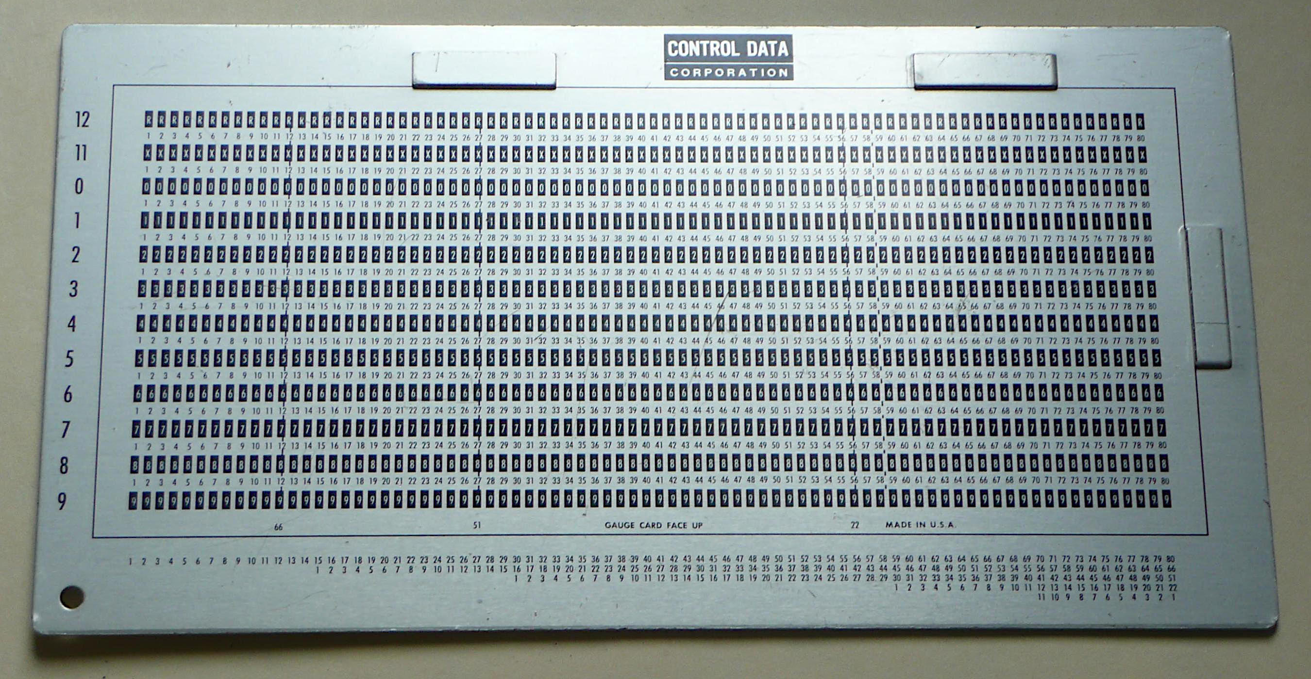
Technicians who had to adjust keypunches and high-speed card punches needed to be able to judge how well the punches were aligned. Manufacturers of punched card machines made card gauges for this purpose. The gauge includes alignment guides to hold a card on the gauge, and the printing on the gauge has black rectangles precisely aligned with each punch position.
If you place a punched card on the gauge, pressed up against the guides, you should see only the black rectangles through each punched hole, and not any of the bright aluminum background. The example card sitting on the gauge in the photo here shows a slight misalignment, visible as a thin stripe of aluminum on the left side of each punched hole. This particular error is small enough that the card will read correctly, but it shows that the punch that it was prepared on did need alignment.
If a card was printed with all the row and column numbers, as is the example card here, the additional printing on the alignment gauge is of little value. Note, however, that many cards were not fully printed. If a programmer wanted to read the data on such a card by eyeball, a card gauge was a very convenient tool because the row number is visible through each punch and the column numbers are clearly printed along the bottom edge of the card.
This particular card gauge, made by CDC (Control Data Corporation) has 5 rows of column numbers across the bottom. The longest row of column numbers is for 80-column cards, but it also shows numbering for shorter cards. 66, 51, 22 and 11-column cards were all supported. Usually, these began as 80 column cards that were perforated, to be torn apart at some point in their life. An 80-column card could be arranged to be torn into a 66 column card and an 11 column stub, or into a 51 column card and a 22 column stub.
Programmers who designed the data formats used on punched cards also tended to design the print formats for the printed output of the card-processing programs. In many cases, printed output was simply printed on green-bar paper, but sometimes, special forms were needed. Paychecks are a good example, but there were many others. Designers of data processing forms needed to think in terms of the layout layout of line printer output, which was usually printed at 10 characters per inch horzontally and 6 characters per inch vertically.
|

|
This etched stainless-steel ruler, sold or perhaps even given away by Lewis Business Forms, Inc, of Jacksonville Florida, was designed and copyrighted by Woodward Associates, Inc, of Fayetteville New York in 1964. The ruler includes an obvious scale in inches, plus a number of other more specialized scales:
In orgaizations where handwritten material was sent off to keypunch clerks (almost always women) to be transcribed onto cards, it was important to write very clearly and to be careful to document indenting and card column usage. It is important to remember that, before the 1970s, typing was considered to be clerical work that professionals such as engineers or mathematicians did not do. Professional typists or keypunch operators, on the other hand, were expected to be very fast and accurate, but they were not expected to understand what they were transcribing.
Coding forms were a natural way to deal with this divide. Programmers were expected to write their code in block capital letters. Coding forms were produced for most programming languages. Languages such as RPG (IBM's Report Program Generator) and many assembly languages had very strict requirements for card column use.
|
IBM's form X28-7327-4, a FORTRAN coding form, is quite simple compared to an assembly language or RPG coding form. In classic FORTRAN, the first 5 columns are reserved for statement numbers, the 6th column is reserved for continuation markers and code may only continue to column 72. The code itself is free-form so no additional column constraints are imposed on the bulk of the card.
The top of the form is relevant for a paperwork sent through the bureaucratic interface to the keypunch staff. You clearly want your cards returned, so a blank for your name is an obvious feature. You might have multiple jobs queued for the keypunch staff, so when you get a batch of cards back punched from some form, you need to know what program they go to. Some keypunch symbols are hard to write, so a little translation table is provided to translate between the symbol you write on the form and the symbol on the key cap of the keypunch. The programmer got to specify what card stock to use, and optionally, specify something to be punched in columns 73 to 80 of each card.
|
The above coding form is much older. It was used by Michael A. Geraghty (1930-2012) when he was a postdoc at MIT's Lincoln Labs in the 1950s. The code on this form resembles assembly language, but it is not written in a formal assembly language. Instead, it is intended for manual translation to machine language. Unlike the coding forms of the 1960s and 1970s, this was not sent off to keypunch, but rather, Mike probably directly translated the material on this form to machine code, while the form itself is designed as an archival record of how he designed the program.
The form itself is huge close to the size of a sheet of newspaper, about 22 by 16 inches, printed on thin drafting paper. The high resolution copy was digitized at 400 pixels per inch. The paper was quite brown and brittle. The color balance of the digitized version was adjusted to increase the legibility.
The large size of this sheet is not uncommon for technical drawings, and the space on the form for the title and author information is structured very much like the title block on an engineering drawing. Mike Geraghty's file folder that held this form also held two diazo prints of this original. Again, this was the printing process routinely used for engineering drawings in the 1950s.
What computer was this for? I can't tell. The code is not translated to binary on this form, and the manuals I have for computers from before the era of formal assembly languages don't document the informal notations used by programmers. The comments in the code do make multiple references to data from cards and to a Flexowriter (referred to as a Flexo), but that's not enough to pin anything down.
In the 1950s and 1960s, programmers were expected to produce schematic drawings documenting the code they produced. This requirement was natural at the time for two distinct reasons:
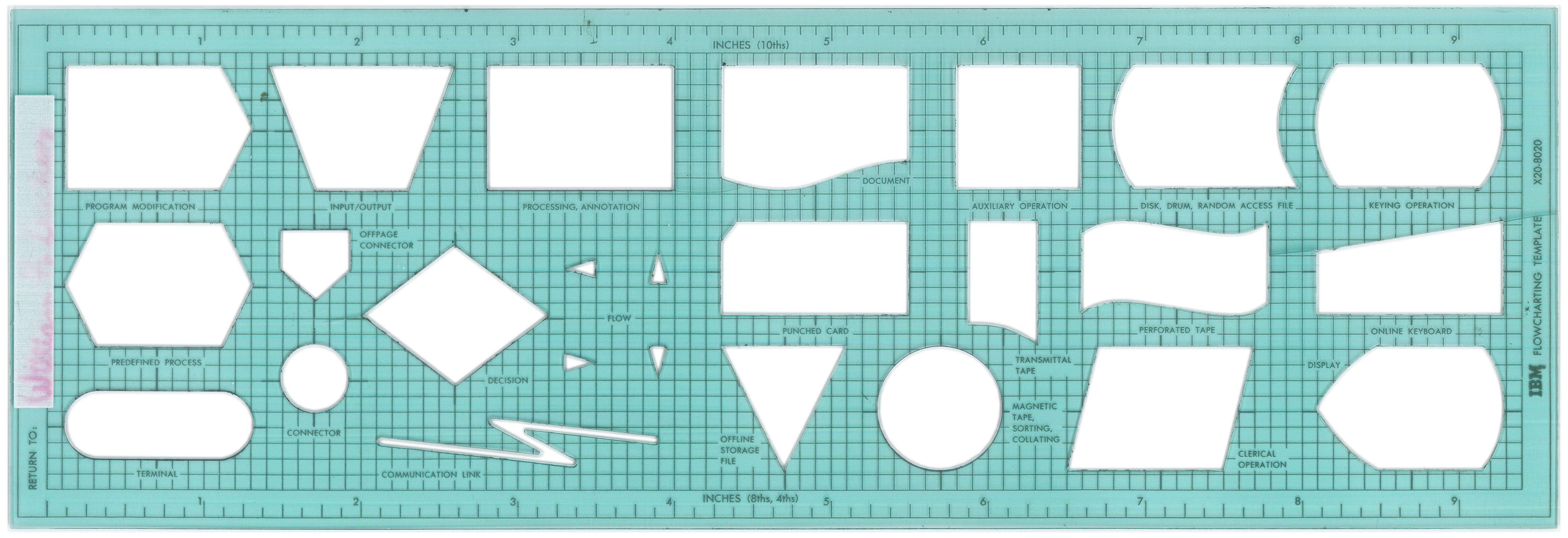
There was a standard for the symbols to use in a flowchart, and naturally, various vendors produced drafting templates to help programmers produce uniform looking versions of these symbols. Similar templates continue to be made today for electrical schematic symbols, digital logic symbols, plumbing and other realms, but flowcharting has become a lost art.
|
|
The two templates shown here were made by (or for) IBM. They have most of the same symbols arranged in a slightly more compact form on the older template. The new one added a few symbols, plus a metric ruler along one edge.
The older template here was originally purchased by William F. Decker, an early graduate of the University of Iowa's computer science department in the 1960s. He managed to save the envelope it came in.

|
|
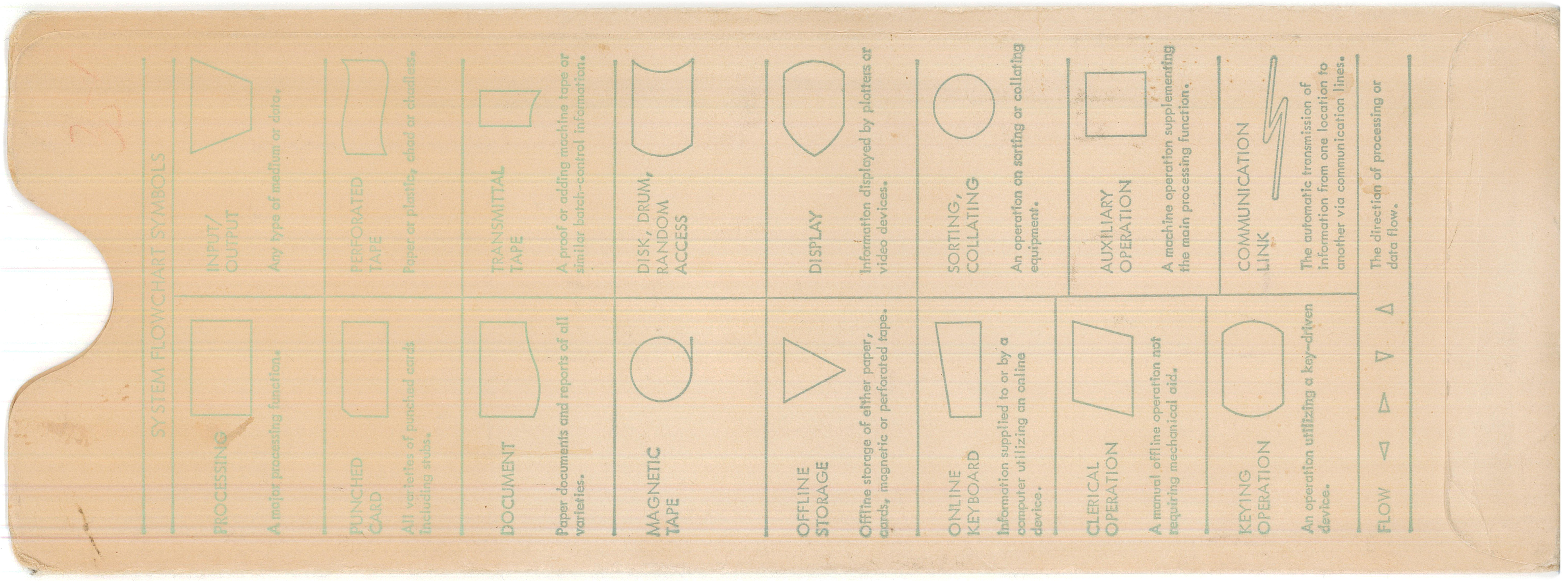
The envelope, printed in green ink on white paper, contains a brief description of the use of each symbol. Side A, the front, refers to the IBM Data Processing Techniques manual (publication C20-8152) and then gives the symbols for program flowcharts. Side B, the rear, gives system flowchart symbols — these can be used to document the data flow through a system or the logical structure of a system.
The paper on the envelope pictured here has oxidized to various shades of brown, and the ink has faded. Fortunately, the content can be recovered by using just the red channel from each image. The links in the text above refer heavily processed images that are surprisingly readable.
It is worth noting that neither the template nor its envelope has a copyright notice. The omission is almost certainly deliberate. It suggests that IBM was far more interested in seeing its work distributed and used than they were in earning money from the purchase of flowchart templates.